
Summary
Inductors are very important components in switching converters, such as energy storage and power filters. There are many types of inductors, such as for different applications (from low frequency to high frequency), or different core materials that affect the characteristics of the inductor, and so on. Inductors used in switching converters are high-frequency magnetic components. However, due to various factors such as materials, operating conditions (such as voltage and current), and ambient temperature, the characteristics and theories presented are quite different. Therefore, in the circuit design, in addition to the basic parameter of the inductance value, the relationship between the impedance of the inductor and the AC resistance and frequency, the core loss and the saturation current characteristics, etc. must still be considered. This article will introduce several important inductor core materials and their characteristics, and also guide power engineers to choose commercially available standard inductors.
Preface
Inductor is an electromagnetic induction component, which is formed by winding a certain number of coils (coil) on a bobbin or core with an insulated wire. This coil is called an inductance coil or Inductor. According to the principle of electromagnetic induction, when the coil and the magnetic field move relative to each other, or the coil generates an alternating magnetic field through an alternating current, an induced voltage will be generated to resist the change of the original magnetic field, and this characteristic of restraining the current change is called inductance.
The formula of inductance value is as formula (1), which is proportional to the magnetic permeability, the square of the winding turns N, and the equivalent magnetic circuit cross-sectional area Ae, and is inversely proportional to the equivalent magnetic circuit length le. There are many types of inductance, each suitable for different applications; the inductance is related to the shape, size, winding method, number of turns, and the type of intermediate magnetic material.

(1)
Depending on the shape of the iron core, the inductance includes toroidal, E core and drum; in terms of iron core material, there are mainly ceramic core and two soft magnetic types. They are ferrite and metallic powder. Depending on the structure or packaging method, there are wire wound, multi-layer, and molded, and the wire wound has non-shielded and half of magnetic glue Shielded (semi-shielded) and shielded (shielded), etc.
The inductor acts like a short circuit in direct current, and presents high impedance to alternating current. The basic uses in circuits include choking, filtering, tuning, and energy storage. In the application of the switching converter, the inductor is the most important energy storage component, and forms a low-pass filter with the output capacitor to reduce the output voltage ripple, so it also plays an important role in the filtering function.
This article will introduce the various core materials of inductors and their characteristics, as well as some of the electrical characteristics of inductors, as an important evaluation reference for selecting inductors during circuit design. In the application example, how to calculate the inductance value and how to choose a commercially available standard inductor will be introduced through practical examples.
Type of core material
Inductors used in switching converters are high-frequency magnetic components. The core material in the center most affects the characteristics of the inductor, such as impedance and frequency, inductance value and frequency, or core saturation characteristics. The following will introduce the comparison of several common iron core materials and their saturation characteristics as an important reference for selecting power inductors:
1. Ceramic core
Ceramic core is one of the common inductance materials. It is mainly used to provide the supporting structure used when winding the coil. It is also called “air core inductor”. Because the iron core used is a non-magnetic material with a very low temperature coefficient, the inductance value is very stable in the operating temperature range. However, due to the non-magnetic material as the medium, the inductance is very low, which is not very suitable for the application of power converters.
2. Ferrite
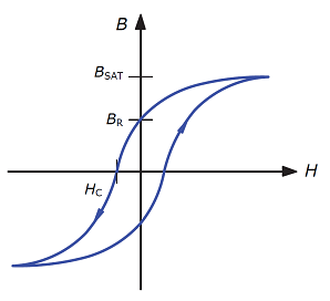
The ferrite core used in general high frequency inductors is a ferrite compound containing nickel zinc (NiZn) or manganese zinc (MnZn), which is a soft magnetic ferromagnetic material with low coercivity. Figure 1 shows the hysteresis curve (BH loop) of a general magnetic core. The coercive force HC of a magnetic material is also called coercive force, which means that when the magnetic material has been magnetized to magnetic saturation, its magnetization (magnetization) is reduced to zero The required magnetic field strength at the time. Lower coercivity means lower resistance to demagnetization and also means lower hysteresis loss.
Manganese-zinc and nickel-zinc ferrites have relatively high relative permeability (μr), about 1500-15000 and 100-1000, respectively. Their high magnetic permeability makes the iron core higher in a certain volume. The inductance. However, the disadvantage is that its tolerable saturation current is low, and once the iron core is saturated, the magnetic permeability will drop sharply. Refer to Figure 4 for the decreasing trend of magnetic permeability of ferrite and powder iron cores when the iron core is saturated. Comparison. When used in power inductors, an air gap will be left in the main magnetic circuit, which can reduce permeability, avoid saturation and store more energy; when the air gap is included, the equivalent relative permeability can be about 20- Between 200. Since the high resistivity of the material itself can reduce the loss caused by eddy current, the loss is lower at high frequencies, and it is more suitable for high-frequency transformers, EMI filter inductors and energy storage inductors of power converters. In terms of operating frequency, nickel-zinc ferrite is suitable for use (>1 MHz), while manganese-zinc ferrite is suitable for lower frequency bands (<2 MHz).
 1
1
Figure 1. The hysteresis curve of the magnetic core (BR: remanence; BSAT: saturation magnetic flux density)
3. Powder iron core
Powder iron cores are also soft-magnetic ferromagnetic materials. They are made of iron powder alloys of different materials or only iron powder. The formula contains non-magnetic materials with different particle sizes, so the saturation curve is relatively gentle. The powder iron core is mostly toroidal. Figure 2 shows the powder iron core and its cross-sectional view.
Common powdered iron cores include iron-nickel-molybdenum alloy (MPP), sendust (Sendust), iron-nickel alloy (high flux) and iron powder core (iron powder). Because of the different components, its characteristics and prices are also different, which affects the choice of inductors. The following will introduce the aforementioned core types and compare their characteristics:
A. Iron-nickel-molybdenum alloy (MPP)
Fe-Ni-Mo alloy is abbreviated as MPP, which is the abbreviation of molypermalloy powder. The relative permeability is about 14-500, and the saturation magnetic flux density is about 7500 Gauss (Gauss), which is higher than the saturation magnetic flux density of ferrite (about 4000-5000 Gauss). Many out. MPP has the smallest iron loss and has the best temperature stability among powder iron cores. When the external DC current reaches the saturation current ISAT, the inductance value decreases slowly without abrupt attenuation. MPP has better performance but higher cost, and is usually used as power inductor and EMI filtering for power converters.
B. Sendust
The iron-silicon-aluminum alloy iron core is an alloy iron core composed of iron, silicon, and aluminum, with a relative magnetic permeability of about 26 to 125. The iron loss is between the iron powder core and MPP and iron-nickel alloy. The saturation magnetic flux density is higher than MPP, about 10500 Gauss. Temperature stability and saturation current characteristics are slightly inferior to MPP and iron-nickel alloy, but better than iron powder core and ferrite core, and the relative cost is cheaper than MPP and iron-nickel alloy. It is mostly used in EMI filtering, power factor correction (PFC) circuits and power inductors of switching power converters.
C. Iron-nickel alloy (high flux)
The iron-nickel alloy core is made of iron and nickel. The relative magnetic permeability is about 14-200. The iron loss and temperature stability are between MPP and iron-silicon-aluminum alloy. The iron-nickel alloy core has the highest saturation magnetic flux density, about 15,000 Gauss, and can withstand higher DC bias currents, and its DC bias characteristics are also better. Application scope: Active power factor correction, energy storage inductance, filter inductance, high frequency transformer of flyback converter, etc.
D. Iron powder
The iron powder core is made of high-purity iron powder particles with very small particles that are insulated from each other. The manufacturing process makes it have a distributed air gap. In addition to the ring shape, the common iron powder core shapes also have E-type and stamping types. The relative magnetic permeability of the iron powder core is about 10 to 75, and the high saturation magnetic flux density is about 15000 Gauss. Among the powder iron cores, the iron powder core has the highest iron loss but the lowest cost.
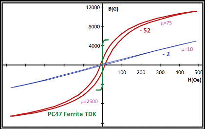
Figure 3 shows the BH curves of PC47 manganese-zinc ferrite manufactured by TDK and powdered iron cores -52 and -2 manufactured by MICROMETALS; the relative magnetic permeability of manganese-zinc ferrite is much higher than that of powdered iron cores and is saturated The magnetic flux density is also very different, the ferrite is about 5000 Gauss and the iron powder core is more than 10000 Gauss.
 3
3
Figure 3. B-H curve of manganese-zinc ferrite and iron powder cores of different materials
In summary, the saturation characteristics of the iron core are different; once the saturation current is exceeded, the magnetic permeability of the ferrite core will drop sharply, while the iron powder core can slowly decrease. Figure 4 shows the magnetic permeability drop characteristics of a powder iron core with the same magnetic permeability and a ferrite with an air gap under different magnetic field strengths. This also explains the inductance of the ferrite core, because the permeability drops sharply when the core is saturated, as can be seen from equation (1), it also causes the inductance to drop sharply; while the powder core with distributed air gap, the magnetic permeability The rate decreases slowly when the iron core is saturated, so the inductance decreases more gently, that is, it has better DC bias characteristics. In the application of power converters, this characteristic is very important; if the slow saturation characteristic of the inductor is not good, the inductor current rises to the saturation current, and the sudden drop in inductance will cause the current stress of the switching crystal to rise sharply, which is easy to cause damage.
4
Figure 4. Magnetic permeability drop characteristics of powder iron core and ferrite iron core with air gap under different magnetic field strength.
Inductor electrical characteristics and package structure
When designing a switching converter and selecting an inductor, the inductance value L, impedance Z, AC resistance ACR and Q value (quality factor), rated current IDC and ISAT, and core loss (core loss) and other important electrical characteristics are all Must be considered. In addition, the packaging structure of the inductor will affect the magnitude of the magnetic leakage, which in turn affects EMI. The following will discuss the above-mentioned characteristics separately as considerations for selecting inductors.
1. Inductance value (L)
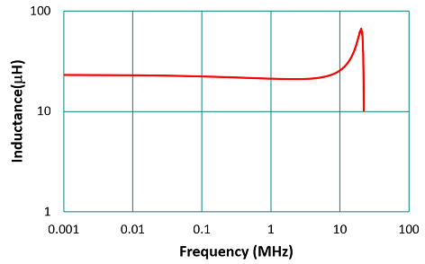
The inductance value of an inductor is the most important basic parameter in circuit design, but it must be checked whether the inductance value is stable at the operating frequency. The nominal value of the inductance is usually measured at 100 kHz or 1 MHz without an external DC bias. And to ensure the possibility of mass automated production, the tolerance of the inductor is usually ±20% (M) and ±30% (N). Figure 5 is the inductance-frequency characteristic graph of Taiyo Yuden inductor NR4018T220M measured with Wayne Kerr’s LCR meter. As shown in the figure, the inductance value curve is relatively flat before 5 MHz, and the inductance value can almost be regarded as a constant. In the high frequency band due to the resonance generated by the parasitic capacitance and inductance, the inductance value will increase. This resonance frequency is called the self-resonant frequency (SRF), which usually needs to be much higher than the operating frequency.
 5
5
Figure 5, Taiyo Yuden NR4018T220M inductance-frequency characteristic measurement diagram
2. Impedance (Z)
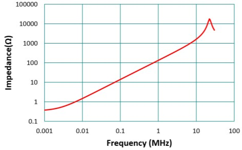
As shown in Figure 6, the impedance diagram can also be seen from the performance of the inductance at different frequencies. The impedance of the inductor is approximately proportional to the frequency (Z=2πfL), so the higher the frequency, the reactance will be much larger than the AC resistance, so the impedance behaves like a pure inductance (phase is 90˚). At high frequencies, due to the parasitic capacitance effect, the self-resonant frequency point of the impedance can be seen. After this point, the impedance drops and becomes capacitive, and the phase gradually changes to -90 ˚.
 6
6
3. Q value and AC resistance (ACR)
Q value in the definition of inductance is the ratio of reactance to resistance, that is, the ratio of the imaginary part to the real part of the impedance, as in formula (2).

(2)
Where XL is the reactance of the inductor, and RL is the AC resistance of the inductor.
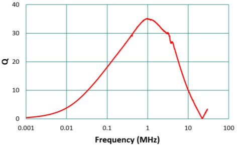
In the low frequency range, the AC resistance is larger than the reactance caused by the inductance, so its Q value is very low; as the frequency increases, the reactance (about 2πfL) becomes larger and larger, even if the resistance due to skin effect (skin effect) and proximity (proximity) effect) The effect becomes larger and larger, and the Q value still increases with frequency; when approaching SRF, the inductive reactance is gradually offset by the capacitive reactance, and the Q value gradually becomes smaller; when the SRF becomes zero, because the inductive reactance and the capacitive reactance are completely the same Disappear. Figure 7 shows the relationship between Q value and frequency of NR4018T220M, and the relationship is in the shape of an inverted bell.
 7
7
Figure 7. The relationship between Q value and frequency of Taiyo Yuden inductor NR4018T220M
In the application frequency band of inductance, the higher the Q value, the better; it means that its reactance is much greater than the AC resistance. Generally speaking, the best Q value is above 40, which means that the quality of the inductor is good. However, generally as the DC bias increases, the inductance value will decrease and the Q value will also decrease. If flat enameled wire or multi-strand enameled wire is used, the skin effect, that is, AC resistance, can be reduced, and the Q value of the inductor can also be increased.
The DC resistance DCR is generally regarded as the DC resistance of the copper wire, and the resistance can be calculated according to the wire diameter and length. However, most of the low current SMD inductors will use ultrasonic welding to make the copper sheet of the SMD at the winding terminal. However, because the copper wire is not long in length and the resistance value is not high, the welding resistance often accounts for a considerable proportion of the overall DC resistance. Taking TDK’s wire-wound SMD inductor CLF6045NIT-1R5N as an example, the measured DC resistance is 14.6mΩ, and the DC resistance calculated based on the wire diameter and length is 12.1mΩ. The results show that this welding resistance accounts for about 17% of the overall DC resistance.
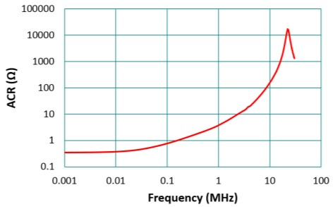
AC resistance ACR has skin effect and proximity effect, which will cause ACR to increase with frequency; in the application of general inductance, because the AC component is much lower than the DC component, the influence caused by ACR is not obvious; but at light load, Because the DC component is reduced, the loss caused by ACR cannot be ignored. The skin effect means that under AC conditions, the current distribution inside the conductor is uneven and concentrated on the surface of the wire, resulting in a reduction in the equivalent wire cross-sectional area, which in turn increases the equivalent resistance of the wire with frequency. In addition, in a wire winding, adjacent wires will cause the addition and subtraction of magnetic fields due to the current, so that the current is concentrated on the surface adjacent to the wire (or the farthest surface, depending on the direction of the current), which also causes equivalent wire interception. The phenomenon that the area decreases and the equivalent resistance increases is the so-called proximity effect; in the inductance application of a multilayer winding, the proximity effect is even more obvious.
 8
8
Figure 8 shows the relationship between AC resistance and frequency of the wire-wound SMD inductor NR4018T220M. At a frequency of 1kHz, the resistance is about 360mΩ; at 100kHz, the resistance rises to 775mΩ; at 10MHz, the resistance value is close to 160Ω. When estimating the copper loss, the calculation must consider the ACR caused by the skin and proximity effects, and modify it to formula (3).
4. Saturation current (ISAT)
Saturation current ISAT is generally the bias current marked when the inductance value is attenuated such as 10%, 30%, or 40%. For air-gap ferrite, because its saturation current characteristic is very rapid, there is not much difference between 10% and 40%. Refer to Figure 4. However, if it is an iron powder core (such as a stamped inductor), the saturation curve is relatively gentle, as shown in Figure 9, the bias current at 10% or 40% of the inductance attenuation is much different, so the saturation current value will be discussed separately for the two types of iron cores as follows .
For an air-gap ferrite, it is reasonable to use ISAT as the upper limit of the maximum inductor current for circuit applications. However, if it is an iron powder core, because of the slow saturation characteristic, there will be no problem even if the maximum current of the application circuit exceeds ISAT. Therefore, this iron core characteristic is most suitable for switching converter applications. Under heavy load, although the inductance value of the inductor is low, as shown in Figure 9, the current ripple factor is high, but the current capacitor current tolerance is high, so it will not be a problem. Under light load, the inductance value of the inductor is larger, which helps to reduce the ripple current of the inductor, thereby reducing the iron loss. Figure 9 compares the saturation current curve of TDK’s wound ferrite SLF7055T1R5N and stamped iron powder core inductor SPM6530T1R5M under the same nominal value of inductance.
9
Figure 9. Saturation current curve of wound ferrite and stamped iron powder core under the same nominal value of inductance
5. Rated current (IDC)
The IDC value is the DC bias when the inductor temperature rises to Tr˚C. The specifications also indicate its DC resistance value RDC at 20˚C. According to the temperature coefficient of the copper wire is about 3,930 ppm, when the temperature of Tr rises, its resistance value is RDC_Tr = RDC (1+0.00393Tr), and its power consumption is PCU = I2DCxRDC. This copper loss is dissipated on the surface of the inductor, and the thermal resistance ΘTH of the inductor can be calculated:
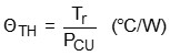 (2)
(2)
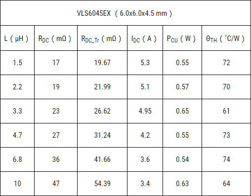
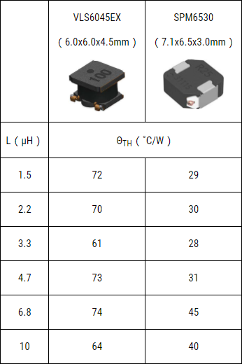
Table 2 refers to the data sheet of the TDK VLS6045EX series (6.0×6.0×4.5mm), and calculates the thermal resistance at a temperature rise of 40˚C. Obviously, for inductors of the same series and size, the calculated thermal resistance is almost the same due to the same surface heat dissipation area; in other words, the rated current IDC of different inductors can be estimated. Different series (packages) of inductors have different thermal resistances. Table 3 compares the thermal resistance of inductors of TDK VLS6045EX series (semi-shielded) and SPM6530 series (molded). The larger the thermal resistance, the higher the temperature rise generated when the inductance flows through the load current; otherwise, the lower.
 (2)
(2)
Table 2. Thermal resistance of VLS6045EX series inductors at a temperature rise of 40˚C
It can be seen from Table 3 that even if the size of the inductors is similar, the thermal resistance of the stamped inductors is low, that is, the heat dissipation is better.
 (3)
(3)
Table 3. Comparison of thermal resistance of different package inductors.
6. Core loss
Core loss, referred to as iron loss, is mainly caused by eddy current loss and hysteresis loss. The size of the eddy current loss mainly depends on whether the core material is easy to “conduct”; if the conductivity is high, that is, the resistivity is low, the eddy current loss is high, and if the resistivity of the ferrite is high, the eddy current loss is relatively low. Eddy current loss is also related to frequency. The higher the frequency, the greater the eddy current loss. Therefore, the core material will determine the proper operating frequency of the core. Generally speaking, the working frequency of iron powder core can reach 1MHz, and the working frequency of ferrite can reach 10MHz. If the operating frequency exceeds this frequency, the eddy current loss will increase rapidly and the iron core temperature will also increase. However, with the rapid development of iron core materials, iron cores with higher operating frequencies should be just around the corner.
Another iron loss is the hysteresis loss, which is proportional to the area enclosed by the hysteresis curve, which is related to the swing amplitude of the AC component of the current; the greater the AC swing, the greater the hysteresis loss.
In the equivalent circuit of an inductor, a resistor connected in parallel with the inductor is often used to express the iron loss. When the frequency is equal to SRF, the inductive reactance and capacitive reactance cancel out, and the equivalent reactance is zero. At this time, the impedance of the inductor is equivalent to the iron loss resistance in series with the winding resistance, and the iron loss resistance is much larger than the winding resistance, so The impedance at SRF is approximately equal to the iron loss resistance. Taking a low-voltage inductor as an example, its iron loss resistance is about 20kΩ. If the effective value voltage at both ends of the inductor is estimated to be 5V, its iron loss is about 1.25mW, which also shows that the larger the iron loss resistance, the better.
7. Shield structure
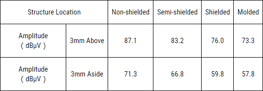
The packaging structure of ferrite inductors includes non-shielded, semi-shielded with magnetic glue, and shielded, and there is a considerable air gap in either of them. Obviously, the air gap will have magnetic leakage, and in the worst case, it will interfere with the surrounding small signal circuits, or if there is a magnetic material nearby, its inductance will also be changed. Another packaging structure is a stamped iron powder inductor. Since there is no gap inside the inductor and the winding structure is solid, the problem of magnetic field dissipation is relatively small. Figure 10 is the use of the FFT function of the RTO 1004 oscilloscope to measure the magnitude of the leakage magnetic field at 3mm above and on the side of the stamped inductor. Table 4 lists the comparison of the leakage magnetic field of different package structure inductors. It can be seen that non-shielded inductors have the most serious magnetic leakage; stamped inductors have the smallest magnetic leakage, showing the best magnetic shielding effect. . The difference in the magnitude of the leakage magnetic field of the inductors of these two structures is about 14dB, which is nearly 5 times.
10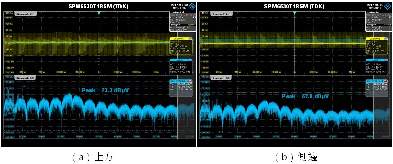
Figure 10. The magnitude of the leakage magnetic field measured at 3mm above and on the side of the stamped inductor
 (4)
(4)
Table 4. Comparison of the leakage magnetic field of different package structure inductors
8. coupling
In some applications, sometimes there are multiple sets of DC converters on the PCB, which are usually arranged next to each other, and their corresponding inductors are also arranged next to each other. If you use a non-shielded or a semi-shielded type with magnetic glue Inductors may be coupled with each other to form EMI interference. Therefore, when placing the inductor, it is recommended to mark the polarity of the inductor first, and connect the starting and winding point of the innermost layer of the inductor to the switching voltage of the converter, such as the VSW of a buck converter, which is the moving point. The outlet terminal is connected to the output capacitor, which is the static point; the copper wire winding therefore forms a certain degree of electric field shielding. In the wiring arrangement of the multiplexer, fixing the polarity of the inductance helps to fix the magnitude of the mutual inductance and avoid some unexpected EMI problems.
Applications:
The previous chapter discussed the core material, package structure, and important electrical characteristics of the inductor. This chapter will explain how to choose the appropriate inductance value of the buck converter and the considerations for choosing a commercially available inductor.
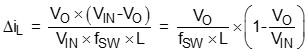
As shown in equation (5), the inductor value and the switching frequency of the converter will affect the inductor ripple current (ΔiL). The inductor ripple current will flow through the output capacitor and affect the ripple current of the output capacitor. Therefore, it will affect the selection of the output capacitor and further affect the ripple size of the output voltage. Furthermore, the inductance value and the output capacitance value will also affect the feedback design of the system and the dynamic response of the load. Choosing a larger inductance value has less current stress on the capacitor, and is also beneficial to reduce output voltage ripple and can store more energy. However, a larger inductance value indicates a larger volume, that is, a higher cost. Therefore, when designing the converter, the design of the inductance value is very important.
 (5)
(5)
It can be seen from formula (5) that when the gap between the input voltage and the output voltage is greater, the inductor ripple current will be greater, which is the worst-case condition of the inductor design. Coupled with other inductive analysis, the inductance design point of the step-down converter should usually be selected under the conditions of maximum input voltage and full load.
When designing the inductance value, it is necessary to make a trade-off between the inductor ripple current and the inductor size, and the ripple current factor (ripple current factor; γ) is defined here, as in formula (6).
 (6)
(6)
Substituting formula (6) into formula (5), the inductance value can be expressed as formula (7).
 (7)
(7)
According to formula (7), when the difference between the input and output voltage is larger, the γ value can be selected larger; on the contrary, if the input and output voltage are closer, the γ value design must be smaller. In order to choose between the inductor ripple current and the size, according to the traditional design experience value, γ is usually 0.2 to 0.5. The following is taking RT7276 as an example to illustrate the calculation of inductance and the selection of commercially available inductors.
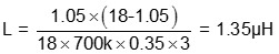
Design example: Designed with RT7276 advanced constant on-time (Advanced Constant On-Time; ACOTTM) synchronous rectification step-down converter, its switching frequency is 700 kHz, the input voltage is 4.5V to 18V, and the output voltage is 1.05V. The full load current is 3A. As mentioned above, the inductance value must be designed under the conditions of the maximum input voltage of 18V and the full load of 3A, the value of γ is taken as 0.35, and the above value is substituted into equation (7), the inductance value is
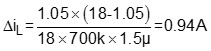
Use an inductor with a conventional nominal inductance value of 1.5 µH. Substitute formula (5) to calculate the inductor ripple current as follows.
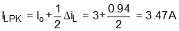
Therefore, the peak current of the inductor is
And the effective value of the inductor current (IRMS) is
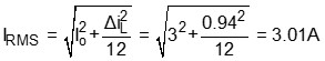
Because the inductor ripple component is small, the effective value of the inductor current is mainly its DC component, and this effective value is used as the basis for selecting the inductor rated current IDC. With 80% derating (derating) design, the inductance requirements are:
L = 1.5 µH (100 kHz), IDC = 3.77 A, ISAT = 4.34 A
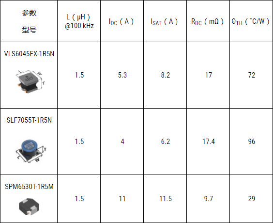
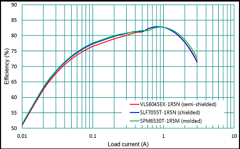
Table 5 lists the available inductors of different series of TDK, similar in size but different in package structure. It can be seen from the table that the saturation current and rated current of the stamped inductor (SPM6530T-1R5M) are large, and the thermal resistance is small and the heat dissipation is good. In addition, according to the discussion in the previous chapter, the core material of the stamped inductor is iron powder core, so it is compared with the ferrite core of the semi-shielded (VLS6045EX-1R5N) and shielded (SLF7055T-1R5N) inductors with magnetic glue. , Has good DC bias characteristics. Figure 11 shows the efficiency comparison of different inductors applied to the RT7276 advanced constant on-time synchronous rectification step-down converter. The results show that the efficiency difference between the three is not significant. If you consider heat dissipation, DC bias characteristics and magnetic field dissipation issues, it is recommended to use SPM6530T-1R5M inductors.
 (5)
(5)
Table 5. Comparison of inductances of different series of TDK
 11
11
Figure 11. Comparison of converter efficiency with different inductors
If you choose the same package structure and inductance value, but smaller size inductors, such as SPM4015T-1R5M (4.4×4.1×1.5mm), although its size is small, but the DC resistance RDC (44.5mΩ) and thermal resistance ΘTH (51˚C) /W) Larger. For converters of the same specifications, the effective value of the current tolerated by the inductor is also the same. Obviously, the DC resistance will reduce the efficiency under heavy load. In addition, a large thermal resistance means poor heat dissipation. Therefore, when choosing an inductor, it is not only necessary to consider the benefits of reduced size, but also to evaluate its accompanying shortcomings.
In conclusion
Inductance is one of the commonly used passive components in switching power converters, which can be used for energy storage and filtering. However, in circuit design, it is not only the inductance value that needs to be paid attention to, but other parameters including AC resistance and Q value, current tolerance, iron core saturation, and package structure, etc., are all parameters that must be considered when choosing an inductor. . These parameters are usually related to the core material, the manufacturing process, and the size and cost. Therefore, this article introduces the characteristics of different iron core materials and how to choose an appropriate inductance as a reference for power supply design.
Post time: Jun-15-2021